

How To Measure Amp Draw 12 Volt

In this commodity we learn how to build a digital voltmeter and a digital ammeter combined circuit module for measuring DC volts and current through unlike ranges, digitally.
Introduction
Electrical parameters like voltage and current are inherently associated with electronics and with electronic engineers.
Whatsoever electronic circuit would be merely incomplete without advisable supply of voltage and current levels.
Our mains Air conditioning supply an alternating voltage at the potentials of 220 V, for implementing these voltages in electronic circuits we incorporate DC power adapters which finer pace down the mains Air conditioning voltages.
Withal, most power supplies don't include power monitoring systems in them, pregnant the units don't incorporate voltage or current meters for displaying the relevant magnitudes.
Mostly the commercial power supplies use simple means to display the voltages similar a calibrated dial or ordinary moving roll blazon meters. These may exist OK every bit long as the involved electronic operations are not disquisitional, but for complex and sensitive electronic operations and troubleshooting, a hi-end monitoring system becomes imperative.
A digital volt meter and an ammeter go very handy for monitoring voltages and current perfectly without compromising prophylactic parameters.
An interesting and authentic digital voltmeter and ammeter excursion has been explained in the present article which can be easily built at home, however the unit volition require a well designed PCB for the sake of accurateness and perfection.
Circuit Performance
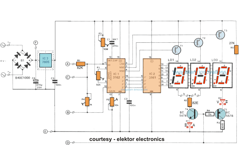
The circuit employs IC 3161 and 3162 for the required processing of the input voltage and current levels.
The processed info can exist directly read over three 7-segment common anode brandish modules.
The circuit requires a 5 volt well regulated power supply department for operating the circuit and should be included without neglect equally the IC strictly requires a 5 volt supply for operating correctly.
The displays are powered by individual transistors which make certain that the displays are lit brightly.
The transistors are BC640, however yous may try other transistors similar 8550 or 187 etc.
The proposed digital voltmeter, ammeter circuit module can be effectively used with a ability supply for indicating the voltage and electric current consumption by the connected load through the fastened modules.
Referring to the excursion diagram below, the 3 digit digital display module is build through the ICs CA 3162 which is an analogue to digital converter IC, and the complementary CA 3161 IC which is BCD to vii segment decoder IC, both these ICs are manufactured past RCA.
How the Displays Work
The 7-segment displays used are common anode blazon and are connected across the shown T1 to T3 transistor drivers for indicating the relevant readings.
The circuit includes the facility for the decimal point selection as per the load specs and range.
For instance in the voltage readouts, when the decimal indicate illuminates at LD3 signifies a 100mV range.
For the current measurement the selection facility enables you lot to choose from a couple ranges, that is through a 0 to 9.99, and the other from 0 to 0.999 amps (using the link b). Which implies that the electric current sensing resistor is either a 0.1 ohm, or a 1 ohm resistor, equally shown in the diagram beneath:
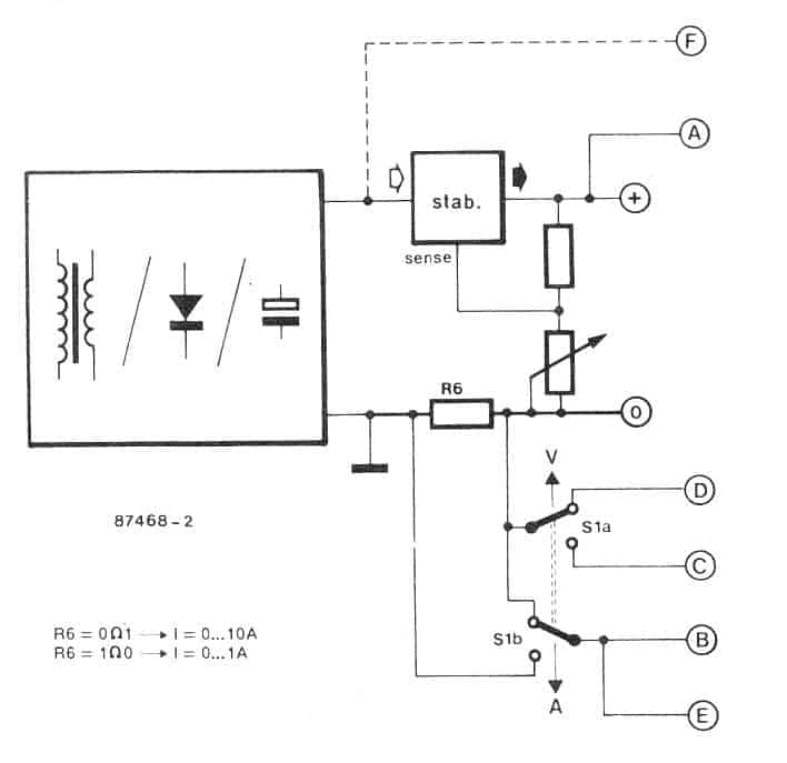
In club to ensure that R6 has no issue on the output voltage this resistor needs to be positioned prior to the voltage divider network which becomes responsible for controlling the output voltage.
S1 which is a DPDT switch is used for selecting either the voltage or the current reading as per the users preference.
With this switch prepare for measuring voltage P4 along with R1 provides an attenuation of effectually 100 for the fed input voltage.
Additionally the point D is enabled at a lower voltage level for assuasive the illumination of the decimal signal on the LS module, and the figure "Five" become brightly illuminated.
With the selection switch held towards the Amp range, the voltage drop acquired beyond the sensing resistor is practical directly over to the points of the Hi-Low inputs of IC1 which is the DAC module.
The significantly low value of the sensing resistors ensures a negligible effect on the voltage divider outcome.
Aligning Ranges for the Displays
You volition find 4 adjustment ranges supplied in the proposed digital voltmeter ammeter circuit module.
P1: for nulling the current range.
P2: For enabling full calibration scale of the current range.
P3: for nulling the voltage range.
P4: For enabling full calibration scale of the voltage range.
It is recommended that the presets are adjusted in the in a higher place guild only wherein P1, and P3 appropriately used for correctly nullifying the respective parameters of the module.
P1 helps to compensate the regulator operating quiescent current consumption value, which results in a pocket-size negative divergence beyond their voltage range, which is in turn effectively compensated by P3.
The voltage/current brandish module works using the unregulated supply from the supply source without any issues (not to exceed 35V max), note the point E and F in the second figure in a higher place. In that case the bridge rectifier B1 tin be eliminated.
The system might be designed like a twofold to acquire concurrent 5 and I readings. It ought to be recognized, nonetheless, that the current sensing resistor is brusk-circuited by means of the ground links each fourth dimension the two devices are provided from the identical source. There are basically 2 methods to defeat this disorder.
The commencement is to claw upwardly the V module from a different source, while the l module from the "host" supply. The 2nd is a lot more graceful and necessitates hard wiring areas Due east to the left side of the current sensing resistor.
Exist aware, although, that the highest possible Five reading in that case turns into 20.0 V (R6 declines l V max.), because the voltage at pin ll unremarkably will not surpass fifty.2 V.
Bigger voltages tend to be showed by choosing the lower current quality, ` i.e., R6 gets to be 0R1. Example: R6 falls 0.5V at a current usage of 5 A, to ensure 1.2 - 0.five = 0.7V continues to exist for the voltage reading, whose optimum display is in that instance 100 x 0.7: 70 V But as before, these kinds of complications simply develop whenever a couple of of these units are employed all in i supply.
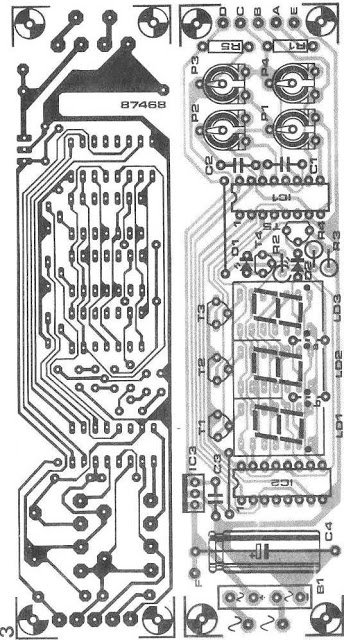
PCB design for making the higher up discussed modules

Source: https://www.homemade-circuits.com/how-to-make-digital-voltmeter-ammeter/
Posted by: merrilledmis1941.blogspot.com
0 Response to "How To Measure Amp Draw 12 Volt"
Post a Comment